
Tel:0086-18253885135
Email: info@beacon-machine.com
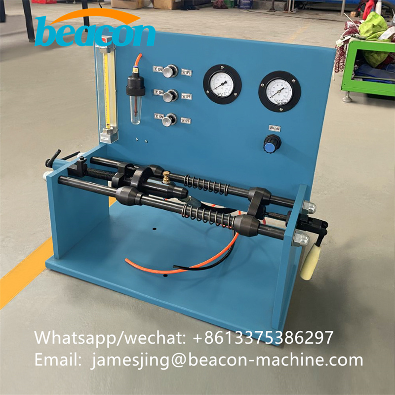
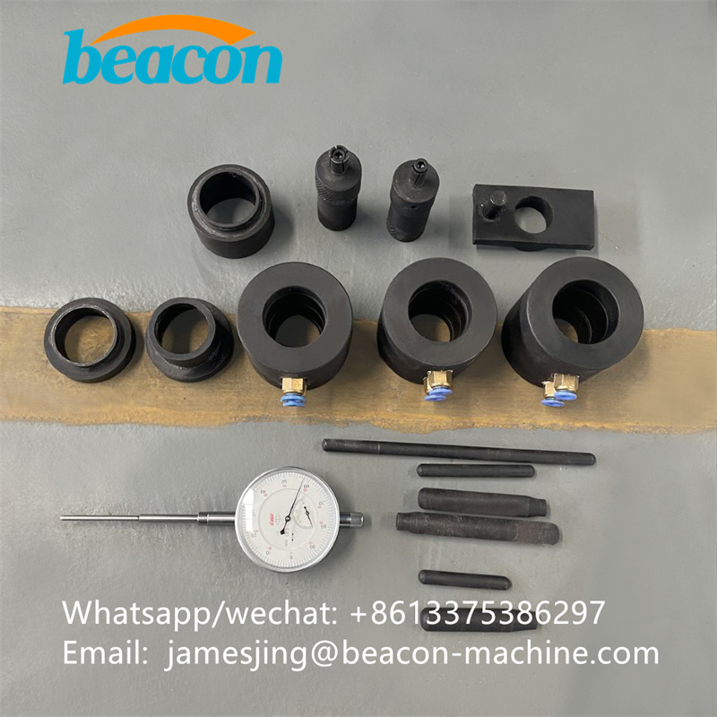
PT302 Common Rail Tester PT Injector Leakage Test Bench For Cummins


PT302 Injector Leakage Tester
(All PT Injectors)
PT301 injector Leakage Tester (Fig. l) was developed as a Standard tool to accurately determine the degree of acceptability of PT injectors.
Plumbing modifications have recently been made which will permit this machine to be used for determining check ball leakage on all PT cylindrical injectors. This topic will provide information relating to the installation, modification, maintenance, altitude compensation and operating instructions for PT301 injector Leakage Tester.
Installation requirements
The following facilities are necessary for acceptable installation of PT301 Injector Leakage Tester:
1. A clean area with good lighting. An enclosed fuel system area is preferred. When a tightly enclosed room is used, due to the extreme sensitivity of the air flowmeter, the ball float may fluctuate slightly when opening or closing the door Except for inaccurate reading during the time when the door is opened and closed, such a room has no adverse effects and is therefore desirable.
2. A workbench of standard height that is not subject to pounding or heavy work. The bench should not have a vise or other shop equipment that is subject to impacts.
3. An air supply of 80 psi (552 kPa) minimum pressure. The air line to PTPM should not be in a location where intermittent pressure drops are caused by actuation of other shop air equipment.
Assembly and Installation of PT301 Injector Leakage Tester.
1. Mount rubber isolation pads to feet with capscrews provided.
2. When pad capscrews are snug, panel must be in a horizontal position to insure proper operation of air flowmeter.
3. Fill bubble checker bowl with injector test oil to mark. Fig. 2.
4. Adjust load cell lock to show 50 pounds force. Fig. 3
Modifications
Some early models of the PT301 Leakage Testers (released prior to this topic) were not plumbed for check ball leakage. Please insure that the plumbing of your PTPM matched the schematic illustrated in Fig. 4. If it does not, reroute the lines to the appropriate valves to update the machine.
Note: It is especially important that the 0.020 inch (0.51mm) orifice be relocated from the plastic tee to the tubing immediately before the bubble checker.