

Test hydraulic pump
Test hydraulic cylinder
Test hydraulic motor
Test hydraulic valve
Tel:0086-18253885135
Email: info@beacon-machine.com
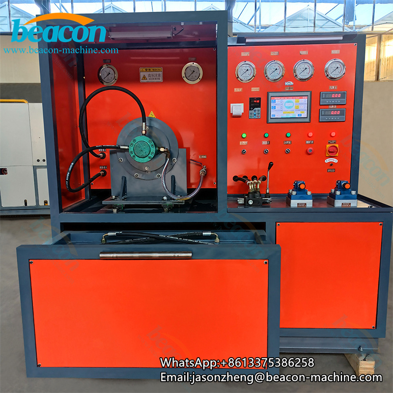
1. Uses: 55KW hydraulic pump test bench
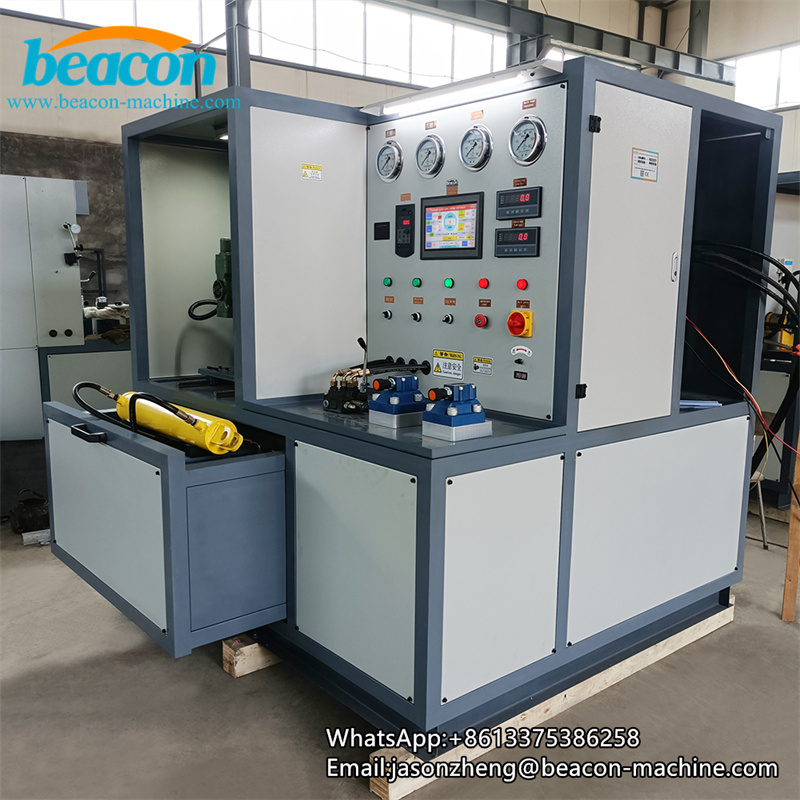
1. It is a comprehensive test table for detecting hydraulic pumps/motors/valves // oil cylinders. It is a special equipment for hydraulic pumps, hydraulic motors, valves, and cylinders. It has the characteristics of compact structure, reliable quality, reasonable design, easy operation and maintenance, and refer to the various technical requirements in GB3766-88 "Smart Technical Conditions for Hydraulic Systems".
2. The hydraulic system of this test table adopts a closed fuel tank structure to allow work in a dusty environment. However, pay attention to the dust on the hydraulic equipment when using it to ensure that the hydraulic system has good heat dissipation and the cleaning of oil Essence
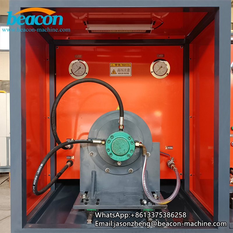
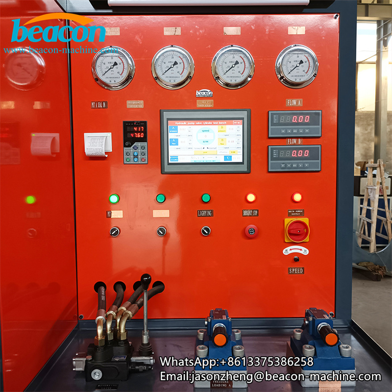
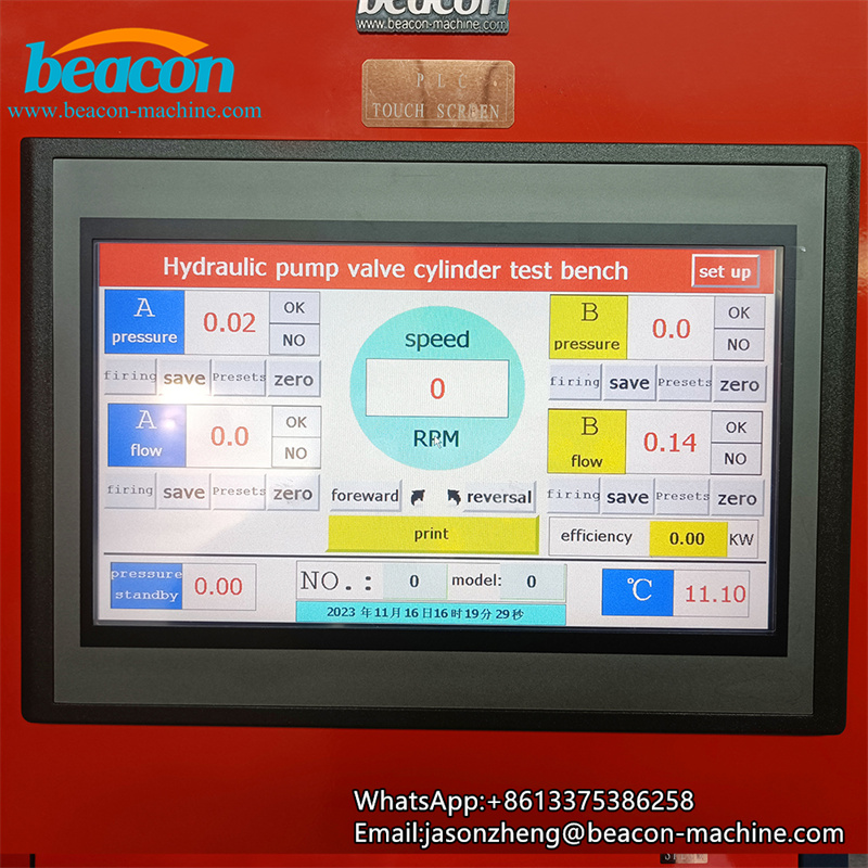
Second, hydraulic pump test stand structural characteristics
1. This device uses an electric motor as the driver system of the entire test table. The testing table is divided into three parts: the motor drive table, the main oil box valve console, the valve and the tank detection table. The installation structure has the advantages of large volume, compact structure, and convenient installation.
2. The integrated oil circuit block design makes the system has less leakage, and the structure is compact, disassembled and convenient.
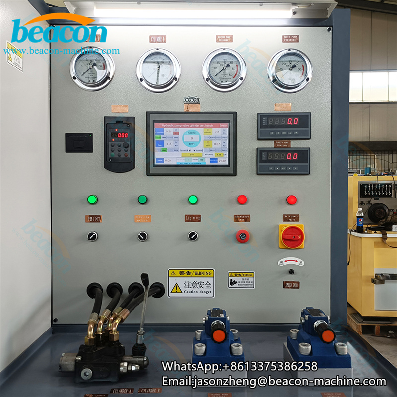
3. The output oil circuit is arranged neatly, clear, and easy to operate.
4. Test the pressure -regulating operation is simple and clear.
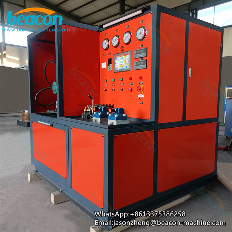
2. The functional configuration and parameters of the hydraulic pump testing machine:
2.1 Driver method: motor driver
2.2 speed: level 4 motor 0--2000r/min; (frequency conversion)
2.3 Loading method: manual dual road loading pressure
2.4 Oil supply method: forced oil supply and self -absorbing oil supply.
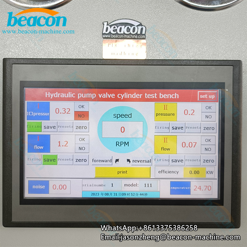
2.5 Display method: Digital table and PLC touch screen display
3.2.6 Operation method: manual operation.
4. Working medium: isovg46 hydraulic oil;
5. The volume of the fuel tank: 1000L actual refueling 800L;
6. Normal cleaning requirements: GB/T14039 19/16 (NAS10)
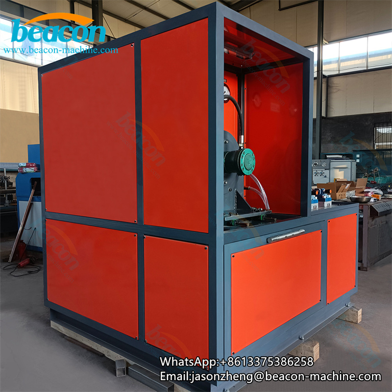
Fourth, installation instructions
1. This hydraulic system should carefully check whether each part of the hydraulic system meets the contract supply scope and whether the design requirements are met, and whether there is damage, or whether the hydraulic system meets the contract.
2. In the installation of each part of this hydraulic system, it should be ensured that all the exposed oil port blocks or bandage should be ensured. Before the equipment installation is installed, it must not fall off to avoid pollution to the hydraulic system.
3. After the hydraulic system is transported to the installation position, it should be fixed firmly on the basis of the design drawings, so as not to loosen, so as not to affect its use performance.
4. After each part of the hydraulic system is in place, please pipe according to the hydraulic operation chart.
5. When installing the connection, be careful not to miss and damage the sealing part.
6. After the hydraulic system is installed, please connect the hydraulic system wiring diagram.
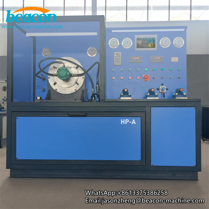
Five, debug instructions
1. After the hydraulic system is installed, first check whether the installation of each part of the hydraulic system is correct, the pipeline connection is correct, and whether the electrical wiring is correct, otherwise it should be processed in time.
2. The cover of the empty filter is covered, and the filter vehicle with the filtering accuracy is not less than 20um to add the hydraulic oil to the liquid level to the upper limit of the hydraulic level through an empty filter, and then restore the empty filter.
3. All the adjustment knobs on the table on the table to zero.
4. Click the motor, if you cannot start, you should re -adjust the line. Pay attention to the direction!
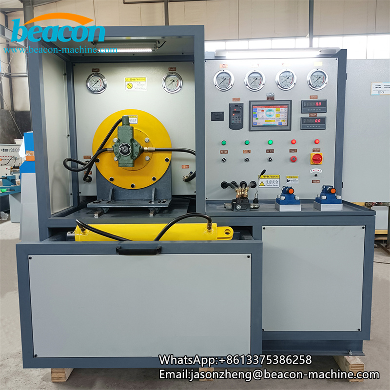
6. Operation control instructions
1. Before use, check whether the adjustment screws of each component and auxiliary parts in the system should be in the correct position, whether the oil is within the indication range of the liquid level meter, and the pipeline joints, fastening screws, etc. Can be put into operation.
2. Before the motor starts and stops, loading, fuel supply, pilot, and speed adjustment left to zero, so that the motor starts or stops in the air load state.
3. In the process of using oil absorption and oil returning oil filter, if it is blocked, please clean or replace it in time.
4. The lock -up overflow valve must not be adjusted at will.
5. The fuel level cannot be lower than the liquid level. When the oil is found, it should be refueling in time.
6. When the system fails, it should be stopped in time.
7. During the use of this hydraulic system, the oil replacement is replaced, component and auxiliary replacement conditions, and the fault treatment situation is recorded in detail to facilitate future maintenance, maintenance and fault analysis.
Seven, maintenance
1. This hydraulic system is debugged. In the future, the hydraulic oil is replaced every other year. After each oil change, the oil tank must be cleaned to replace the oil filter element to ensure the normal operation of the hydraulic system.
2. During the use process, check the oil filter at any time and clean or replace the filter element in time.
3. This hydraulic system should usually always be prone to damage parts, components, and auxiliary spare parts in order to deal with faults in a timely manner.
8. Common faults and treatment
Fault solve
1.Can't load the pressure
1.Check the spinning direction of the pump pump (the electricity of the computer's inspection ratio overflow valve)
2、No traffic, or inaccurate traffic
2、Check the flow meter or flow table, re -effective
3、There are abnormal noise in the test liquid pressure pump and motor,
3、Check the unidirectional valve, the pressure regulating valve has foreign body impurities
3.The jitter pressure is unstable stuck to block, and clean up or replace
Nine, accessories and easy loss parts
In the system, the valve is loaded, the unidirectional valve and the filter element are easy to be damaged.
Weight :3-4t (theoretical weight)
Dimensions: Test Power Channel: 2000X2000X1800mm
Driver power: 55KW-level 4
Auxiliary motor 5.5kW, low -voltage oil supply pump 10 pump pump 10 plunger pumps
The highest oil supply pressure is up to 20MPa
System maximum pressure: 30MPa
System limit pressure; 30MPa
Maximum displacement: 300-400L/min