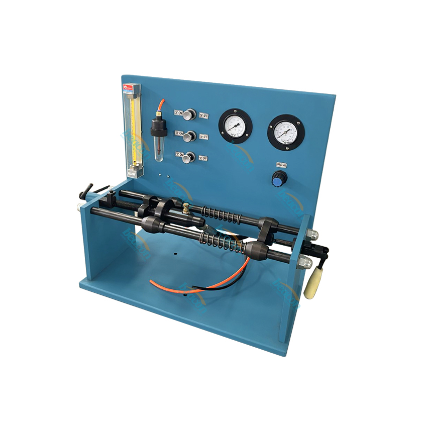
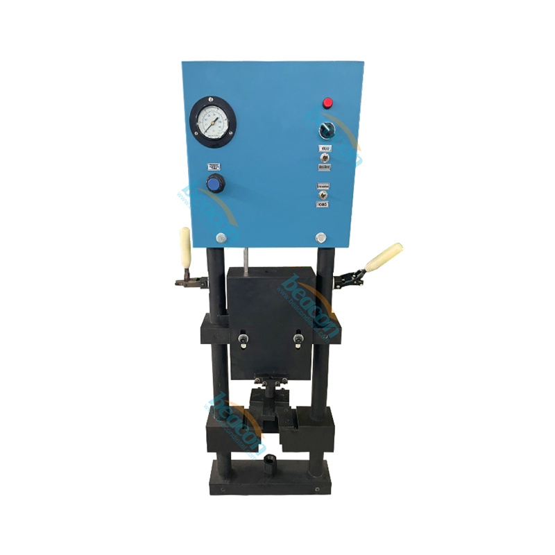
Top Stop Setting Fixture – All PT (type D), STC (HBT),Hyperbar Top Stop Injectors
Tel:0086-18253885135
Email: info@beacon-machine.com
|
REFNO |
PART NO. |
DESCPTION |
QTY |
|
1 |
|
Control panel |
1 |
|
2 |
|
Upper plate |
1 |
|
3 |
|
Lower plate |
1 |
|
4 |
|
Side rails |
2 |
|
5 |
|
Bottom plate |
1 |
|
6 |
|
Center plunge |
1 |
|
7 |
3822745 |
Injector stop nut |
1 |
|
8 |
|
Indicator arm |
1 |
|
9 |
|
20LB.Dead weight |
1 |
|
10 |
3375391 |
Overcenter Clamp |
2 |
|
11
|
|
Measurement System Mounting Plate |
1
|
|
12 |
3822727 |
L-10 Adapter |
1 |
|
13 |
3822726 |
Holding Bracket |
1 |
|
14 |
205462 |
K Injector Plunger Link |
1 |
|
15
|
3025181or 3052233 |
K-STC Injector Plunger Link |
1 1 |
|
16 |
3822730 |
The Indicator |
1 |
|
17 |
|
|
1 |
|
18 |
|
Connecting Cord |
1 |
|
19 |
|
Power cord |
1 |
|
20 |
3822733 |
Presetter Mounting Screws |
2 |
The fixture is available in a kit as Part No.3822732. The kit includes the fixture and the following tools:
3375166 Crowsfoot wrench
3376867 Crowsfoot wrench
3822526 Crowsfoot wrench
3375165 NT Stop Screw Adjusting Tool
3376867 L-10 Stop Screw Adjusting Tool
ST-1072 1 1/4 Crowsfoot

Assembly and Installation
The fixture must be assembles as follows for proper operation.
1.Remove the fixture from the packing crate. The bottom of the fixture has for 1/2〞-13 UNC tapped holes. Use a cap screw length that will allow one inch of the cap screw to screw into the bottom plate of the fixture. Tighten the cap screws to 54 N·m (40 ft-lbs).
2. Place the upper toggle switch (3) on the control panel to the “LOWER” position. Place the lower toggle switch (4) on the control panel to the “UNLAD” position
3. Connect the air supply line into the 1/4 NPT female port of the air filter in the rear of the fixture. The air must be above 550 kPa (80psl) for the proper fixture operation.
4. Keep your hands away from the fixture. Turn the air supply on.
5. Adjust the pressure-adjusting knob (2) on the control panel until the pressure gauge shows 550±20 kPa (80±3 psi). This pressure must be maintained at all times during the fixture operation.
6. Move the upper toggle switch (3) to “RAISE”. This will raise the weight and plunger assembly.
7. Place the tip of the Indicator into the hole in the holding clamp at the bottom of the mounting plate. Lower the indicator until it bottoms against the washer welded to the bottom of the clamp. Tighten the clamping screw.
8. Plug the power cord into the top of the presetter, and the other end into an 220V, 50HZ, electrical outlet.
9. Every fixture’s have the number that is mm.
Note: The fixture that is shipped to non-U.S. countries will be equipped with measurement system appropriate for that country’s electrical source.
Everyone had the number only.

 Language